
When a commercial vehicle air compressor head gasket fails repeatedly after replacement, technicians must investigate beyond the seal itself. A new kit provides the required barrier but cannot overcome systemic pneumatic or thermal faults. Identifying exactly why an air compressor head gasket fails requires evaluating the entire system. This guide covers seven critical diagnostic areas for heavy-duty applications.
Estimated reading time: 7–9 minutes.
Table of Contents
For purchasing discipline, read the gasket supplier approval guide. Its evidence and traceability checks complement this fault investigation; it is not a compressor repair procedure.
Safely Identifying the Failure
Before disassembly, qualified personnel must park safely, chock the wheels, isolate power, allow the unit to cool and release all stored pressure using the applicable service procedure. Drain coolant only as required by that procedure. A vehicle with an unresolved brake-air supply fault must not return to road service.
Differentiating external leaks from unloading issues prevents unnecessary teardowns. Diagnostic tools only reveal evidence of leaks; they do not diagnose the root cause. Pressure state testing must only be conducted by qualified personnel following OEM specifications. Accurately documenting how the air compressor head gasket fails guides the subsequent system inspection.
| Observation | What it does not prove | Next evidence |
|---|---|---|
| Leak near the head joint | That the gasket alone caused it | Locate the leak using the approved test procedure |
| Slow air build-up | That the head gasket is defective | Follow the system-level troubleshooting procedure |
| Oil or moisture downstream | A specific internal failure | Evaluate the compressor and connected air system |

Cooling System Deficiencies
Review the cooling arrangement fitted to the actual compressor. Restrictions, damaged lines or inadequate heat rejection can contribute to abnormal temperatures. Check the relevant supply and return paths, coolant condition and other cooling provisions against the manufacturer’s instructions. Do not conclude that a particular temperature limit was exceeded from appearance alone.
When an air compressor head gasket fails and heat stress is suspected, retain photographs and available operating history. Hardening or discoloration is a clue, not proof of the cause. Investigate cooling performance and operating duty before deciding whether the gasket, a connected system fault or several factors contributed.
| Cooling Component | Inspection Focus | Corrective Goal |
|---|---|---|
| Supply Lines | Check for kinks or internal blockage | Ensure unrestricted coolant flow |
| Return Ports | Inspect for scale or sludge buildup | Maintain proper thermal dissipation |
| Coolant Quality | Verify mixture matches engine specs | Prevent internal rust and scaling |
Discharge Line Restriction
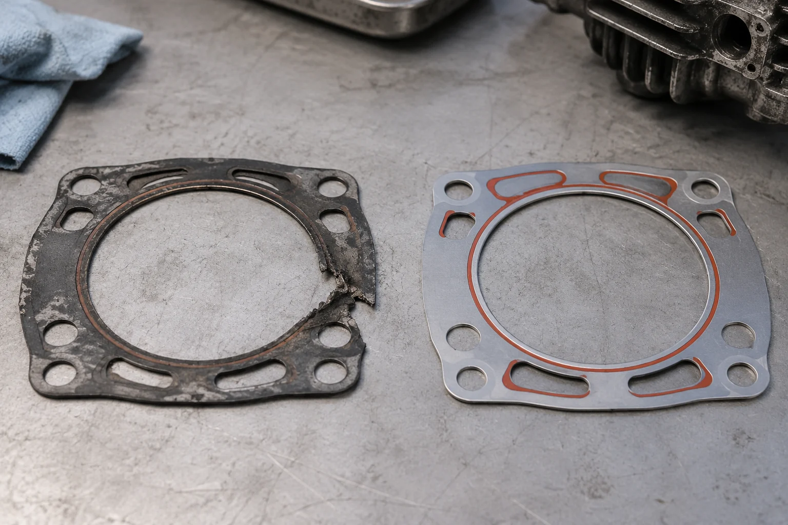
A restricted discharge path can create abnormal compressor loading. Bendix troubleshooting guidance highlights the discharge line between the compressor and air dryer as an important check during air-build-up complaints. Use the applicable service data to identify restrictions and determine the approved remedy.
Never bypass, defeat or substitute an unspecified safety valve. If an air compressor head gasket fails and a discharge restriction is suspected, qualified personnel should inspect the relevant routing after safe isolation and depressurization. Follow the manufacturer’s criteria for cleaning, service or replacement rather than assuming a gasket change resolves the problem.
| System Area | Risk Factor | Maintenance Action |
|---|---|---|
| Discharge line | Kinks, deposits or an identified restriction | Follow model-specific inspection and remedy |
| Connected air system | An unresolved air-build-up complaint | Use the complete system troubleshooting sequence |
| Safety protection | Missing, incorrect or altered components | Restore the specified configuration; never bypass |
Load Control and Unloader Faults
Depending on the system design, governor, unloader and control-circuit faults can prevent normal loaded and unloaded operation. Excessive system demand or leakage may also increase compressor duty. Evaluate the complete control arrangement rather than assuming that one sticking component explains every repeated head-joint leak.
When an air compressor head gasket fails alongside abnormal cycling, record the symptoms and review the applicable control tests. Verify operation using the OEM procedure and required equipment; do not adjust pressure settings speculatively. A confirmed control fault needs correction, but the replacement gasket and installation still require independent inspection.
| Control Component | Operational Risk | Diagnostic Focus |
|---|---|---|
| Governor | Fails to signal cut-out pressure | Check air line and pressure settings |
| Unloader Pistons | Stuck in the pumping position | Inspect for binding or carbon debris |
| Control Lines | Pinched or leaking signal air | Verify line integrity to governor |
Mating Surface Deformation
Commercial compressor heads are subject to severe thermal cycling, which can eventually distort the cast iron or aluminum mating surfaces. A new gasket should not be used to compensate for a mating surface outside its approved limits. Surface irregularities must be addressed to achieve proper clamping force distribution.
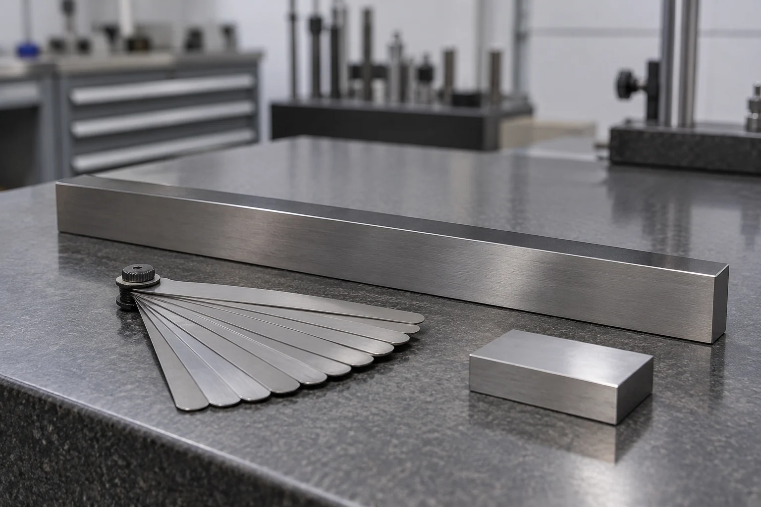
Technicians must carefully clean the mating surfaces without causing gouges or removing base metal. After cleaning, the flatness of the cylinder head and block must be measured against the specific tolerances listed in the OEM service manual. Confirm the manufacturer’s repair or replacement criteria before reassembly; machining may not be an approved option.
| Surface Condition | Potential Cause | Required Response |
|---|---|---|
| Warpage | Severe overheating or improper torque | Measure against specific OEM tolerances |
| Gouging | Use of aggressive metal scrapers | Evaluate for machining or replacement |
| Residual Material | Incomplete cleaning of old seal | Remove safely without chemical damage |
Incorrect Parts and Fitment
Heavy-duty engines undergo numerous accessory changes during their operational lifespan. Relying solely on the engine serial number is insufficient for compressor components, as the ESN cannot substitute for the actual compressor model or part number. The specific tag on the compressor body dictates the correct internal sealing requirements.
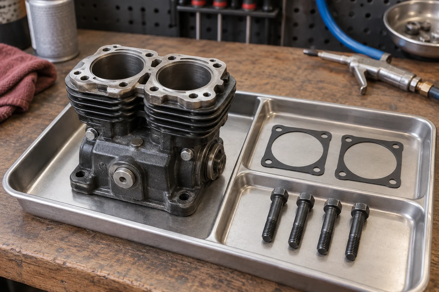
An incorrect part can have the wrong profile, construction or passage layout for the compressor. Compare the quoted reference and kit contents with the actual identification and applicable parts information. Visual similarity supports inspection but cannot establish material suitability or service approval. Hold a mismatch for clarification before assembly.
| Identifier Type | Information Provided | Limitation |
|---|---|---|
| Engine Serial Number | Identifies base engine build | Does not confirm current compressor |
| Compressor Tag | Exact model and assembly number | Required for correct parts lookup |
| Visual Comparison | Confirms port alignment and shape | Cannot verify internal material specs |
Assembly and Torque Errors
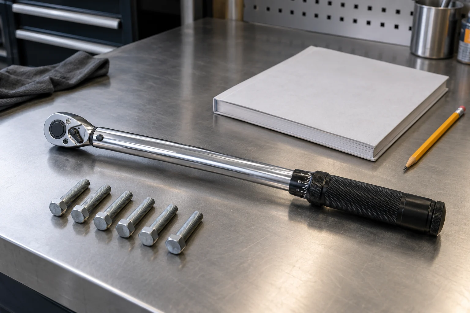
Use the applicable compressor service instructions for surface preparation, fastener assessment, tightening and any permitted sealing compound. Do not infer a universal cross-pattern or reuse rule from another design. Inspect the replacement parts for damage and verify their identity before beginning assembly so an installation problem is not confused with a sourcing error.
When an air compressor head gasket fails soon after repair, preserve the old part and the installation record. Damage patterns may guide investigation but do not prove bolt torque or sealant was the sole cause. Review the stated procedure, tools, surface condition and part reference alongside cooling and air-system findings.
| Assembly Variable | Common Error | Professional Standard |
|---|---|---|
| Fasteners | Reusing stretched or damaged bolts | Inspect threads and replace if necessary |
| Clamping Force | Guessing torque or sequence | Strictly follow OEM service manual values |
| Sealants | Adding a compound without approval | Use only the specified installation method |
Repeat-Failure Evidence Checklist
Repeat-Failure Evidence Checklist
Use only after safe isolation. This tool records investigation areas; it does not diagnose a failure or authorize road use.
Frequently Asked Questions
Can the engine ESN guarantee the correct compressor parts?
No. While the ESN identifies the base engine, it cannot replace the actual air compressor model or part number. Always read the identification tag directly on the compressor body.
How should the vehicle be secured before servicing the compressor?
Before disassembly, qualified personnel must park safely, chock the wheels, isolate power, allow the unit to cool and release all stored pressure using the applicable service procedure. Drain coolant only as required by that procedure. A vehicle with an unresolved brake-air supply fault must not return to road service.
Why is inspecting the discharge line necessary during a gasket replacement?
A restriction or other fault in the discharge path can affect compressor operation. Inspect the connected system using the applicable manufacturer’s procedure rather than treating the gasket as an isolated component.
What determines the correct flatness tolerance for the cylinder head?
Surface flatness must be evaluated against the specific tolerances published in the OEM service manual for that exact compressor model, not by using generic dimensional rules.
Make the Next Decision on Evidence
When an air compressor head gasket fails repeatedly, keep the part, installation and connected systems in the same investigation. Confirm the failure location, cooling, discharge path, control operation, surfaces, correct parts and assembly record. A qualified technician should resolve the evidence and complete the required operational checks before the vehicle returns to service.
Use the gasket product range for general sourcing context, then send the compressor identification, failed-part photographs and required sealing scope to discuss a specific inquiry. Confirm availability and application in writing.
Watch Bendix Tech Talk: Air Compressor Diagnosis for commercial-vehicle air-system context. This older training video supplements, but does not replace, current service data for your compressor.